Mini Project.

When I was set the task of developing a project for the end of robotics, I reallly wanted to do something that was relevant to me. As I have a great interest in playing cards I decided to try and develop a card dealer that could work for three players. The game of choice that I wanted the car dealer to deal would be Texas Hold’em. For anyone not familer with the game, here you go: http://www.texasholdem-poker.com/beginnersintro

So after deciding on the project I had to come up with a design that would work for the resouces and technology that I had available to me:

  • DC Motor
  • Stepper Motor
  • Servo
  • Distance Sensor
  • dsPic

My thinking behind it was to try and keep it as simple as possible(not to over complicate things) but it would still work efficiently.

Design Proocess.

So after looking at the Motors available to me, I decided to go with the Stepper Motor to rotate the dealer to the approiate angle. I decided on this motor because it is quite easy to motor the motor to precise angles, also the servo can do this with possibly greater speed but after looking up the both motors datasheet, the stepper motor prevailed due to its greater torque, which would b a valuable commodity when having to rotate the base.

Next was probably the hardest part how to actually despence the cards to the players. After alot of thinking and keeping in mind to try and keep it simple, I came up with just two rollers driven by a DC motor that would be continuously going so all you would have to do is to feed a card into it and hopefully it would shoot the card out.

So that only left me with actually feeding the card into the rollers. I decided to do this with another DC motor by pulseing it on and off at a given time. This motor would be connected to a roller hovering above the cards.

I decided to make the structure out of balsa wood due to its light weight. I got a bag of it from an Arts and Craft shop. It would be joined together using a hot glue gun.

So with the structure nailed down albiet only in the head I decided to move on to the code.

Code

Before I started to write the code for this, I needed to decided on what angles I wanted the stepper to move to. The full spectrum of movement I retriscted to 180 degrees.Starting position at 0 degrees.

So with three players playing,I put the:

  •  Players 60 degrees apart.( three players).Player 1 @ 60 dergees ,Player 2 @ 120 dergrees, Player 3 @ 180 degrees.
  • The burn cards to be dropped at 45 degrees.
  • Flops cards to be dropped at 60, 70 and 80 degrees.
  • Turn card to be dropped at 85 degrees.
  • River card to be dropped at 95 degrees.

So when the stepper motor is at each of these points, the DC motor will pulse and drive a card into the front rollers.

Below is my final code used:

//
// dsPIC30F4011 Card Dealer Mini Project
// Written by James McMahon
// Last updated 10-12-2013
//

#include <xc.h>
#include <libpic30.h>

// Configuration settings
_FOSC(CSW_FSCM_OFF & FRC_PLL16); // Fosc=16x7.5MHz, Fcy=30MHz
_FWDT(WDT_OFF);                  // Watchdog timer off
_FBORPOR(MCLR_DIS);              // Disable reset pin

// Function prototypes
void step_forward();
void step_back();
void steps(int n);

// global variables
double step_angle;
long step_time;

int main()
{
    // Make all port D & B pins outputs.
    TRISD = 0;
    TRISB = 0;

    // Stepper properties
    step_time = 300000L; // 10ms
    step_angle = 0.17578125; // 360.0 divided by 2048

    while(1)
    {

		steps(60 / step_angle); __delay32(30000000);	//  step 1..player 1 1st card
		LATB=0b0001;__delay32(20000000);
		LATB=0b0000;__delay32(30000000);
		steps(60 / step_angle); __delay32(30000000);	//  step 2..player 2 1st card
		LATB=0b0001;__delay32(20000000);
		LATB=0b0000;__delay32(30000000);
		steps(60 / step_angle); __delay32(30000000);	//  step 3..player 3 1st card
		LATB=0b0001;__delay32(20000000);
		LATB=0b0000;__delay32(30000000);
		steps(-180 / step_angle); __delay32(30000000);	//  step 4 ..return to the start
		LATB=0b0000;__delay32(30000000);
		steps(60 / step_angle); __delay32(30000000);	//  step 5..player 1 2nd card
		LATB=0b0001;__delay32(20000000);
		LATB=0b0000;__delay32(30000000);
		steps(60 / step_angle); __delay32(30000000);	//  step 6..player 2 2st card
		LATB=0b0001;__delay32(20000000);
		LATB=0b0000;__delay32(30000000);
		steps(60 / step_angle); __delay32(30000000);	//  step 7..player 3 2nd card
		LATB=0b0001;__delay32(20000000);
		LATB=0b0000;__delay32(30000000);
		steps(-180 / step_angle);			//  step 8..return to the start piont

		steps(45 / step_angle); __delay32(30000000);	//  step 9..burn 1st card
		LATB=0b0001;__delay32(20000000);
		LATB=0b0000;__delay32(30000000);
		steps(15 / step_angle); __delay32(30000000);	//  step 10..flop 1st card
		LATB=0b0001;__delay32(20000000);
		LATB=0b0000;__delay32(30000000);
		steps(10/ step_angle);  __delay32(30000000);	//  step 11..flop 2nd card
		LATB=0b0001;__delay32(20000000);
		LATB=0b0000;__delay32(30000000);
		steps(10/ step_angle);  __delay32(30000000);	//  step 12..flop 3rd card
		LATB=0b0001;__delay32(20000000);
		LATB=0b0000;__delay32(30000000);
		steps(-35 / step_angle); __delay32(30000000);	//  step 13..burn 2nd card
		LATB=0b0001;__delay32(20000000);
		LATB=0b0000;__delay32(30000000);
		steps(40 / step_angle); __delay32(30000000);	//  step 14..the turn card
		LATB=0b0001;__delay32(20000000);
		LATB=0b0000;__delay32(30000000);
		steps(-40/ step_angle); __delay32(30000000);	//  step 15..burn 3rd card
		LATD=0b0001;__delay32(20000000);
		LATB=0b0000;__delay32(30000000);
		steps(50/ step_angle); __delay32(30000000);		//  step 16..the river card
		LATB=0b0001;__delay32(20000000);
		LATB=0b0000;__delay32(30000000);
		steps(-100/ step_angle); __delay32(90000000);	//  step 17..return to the start point
		steps(0/ step_angle); __delay32(960000000);		//  step 18..finished

    }
    return 0;
}

void steps(int n)
{
	if (n > 0)
	{
		while (n > 0)
		{
			step_forward();
			n = n - 1;
		}
	}
	else
	{
		while (n < 0)
		{
			step_back();
			n = n + 1;
		}
	}
}

void step_forward()
{
    // Turn off the previous phase and turn
    // on the next one.
    if (LATD == 0b0001) LATD = 0b0010;
    else if (LATD == 0b0010) LATD = 0b0100;
    else if (LATD == 0b0100) LATD = 0b1000;
    else if (LATD == 0b1000) LATD = 0b0001;
    else LATD = 0b0001;

    // Delay to allow rotor to move.
    __delay32(step_time);
}

void step_back()
{
    // Turn off the previous phase and turn
    // on the next one.
    if (LATD == 0b0001) LATD = 0b1000;
    else if (LATD == 0b0010) LATD = 0b0001;
    else if (LATD == 0b0100) LATD = 0b0010;
    else if (LATD == 0b1000) LATD = 0b0100;
    else LATD = 0b0001;

    // Delay to allow rotor to move.
    __delay32(step_time);
}

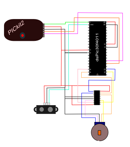
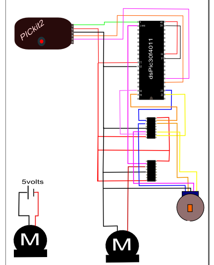
Circuit Diagram
Capture456

Building Process

Balsa Wood and Hot Glue (Excellent stuff to work with, easy to manipulate).9

20131210_223314_LLS

Balsa Wood Used

20131210_223341_LLS

Here you can see the two front roller, they are driven by the shaft that is extended to the right, motor will be attached to there.

Also you can see that there are elastic bands round the rollers, these are used to rotate the top roller. Have the bands(very left & very right) in a 8 shape so that the top roller runs in opposite direction.The other two bands in the middle are there just for traction reasons.

20131210_223400_LLS

In this photo you can see the funnel type guides. These will make sure that the position of the card going into the rollers is correct.

20131210_223451_LLS

20131210_223505_LLS

Position of cards on platform.

20131211_233502

With motors in place.

20131211_233519

  In this photo you can see the motor and roller that feed the two front rotors. I used hurling grip around the roller for traction.

20131219_121448

20131219_121340

Build up a frame around the motor shaft

20131219_121058

Spring underneath the cards to keep upwards force on the rollerso that there is always a card in contact with the roller.

20131219_121415

Used a Connector to attach the shaft of the motor to the roller shaft.

20131219_120924

Stepper motor glued to board. Also thsi is my revised version of the connection on the stepper motor to the dealer. My first attempt was to build a frame up around the shaft of the stepper but it ended up spinning inside it. This way gave the stepper more grip.

20131219_121603

Slot for stepper motor underneath frame.

20131212_190308

Finished model

20131212_160525[1]

Here are a few videos:

In these first 2 videos you can see the basic fuction of the dealer but also you can see the way the stepper motor is moving the dealer as well as I had hoped.This was due to the stepper spinning inside the mount I had made first.

These videos are of the dealer with the revised connection to the stepper motor. As you can see it moves alot smoother but still there could be better with a larger stepper.


Conclusion

There are a few things I would do differently, the rollers at the front,I would use gears instead of elastic bands. The bands worked well but the amount of time in the early stages where the elastic bands would roll off and would take alot of patience and time trying to coax the band back up on the roller.

The next thing I would change would be the size of the stepper motor that I used, I felt that it was a tad bit small. But the major problem I encountered was the wires coming from all the motors would get caught in the structure, thus restricting the movement.

There are also alot more features that I could add to this in the futre, like distance sensor to locate a player. Also if you could develop way to turn the cards for the flop, river and turn cards.I think this could bdone by using an axilwith a servo to rotate the deck of cards. But that would take a bit more thinking.

Overall thought I am happy the way it turned out and I really enjoyed the building and the seeing your plans coming together and it working out for once. Hope you enjoyed. Bye now.
Sensor

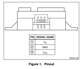
Range Sensor(Sharp GP2D12)

During my robotics I used this sensor the most. I used it on both my DC Motor and Stepper Motor applications.

Here are some of its parameters:

FEATURES
• Analog output
• Effective Range: 10 to 80 cm
• LED pulse cycle duration: 32 ms
• Typical response time: 39 ms
• Typical start up delay: 44 ms
• Average current consumption: 33 mA
• Detection area diameter @ 80 cm: 6 cm

2

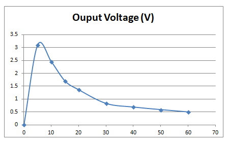
Range Sensor(Sharp GP2D12) . After the initial testing of it and when compared to the datasheet of the sensor, which was got online http://www.sharpsma.com/webfm_send/1203, matched up pretty well. Here are the results of the range sensor:


gp2d12

Distance (cm)

Ouput Voltage (V)

0 0
5 3.1
10 2.45
15 1.7
20 1.36
30 0.83
40 0.69
50 0.59
60 0.5

Capture251

Y-Axis (Voltage)      X-Axis (distance)

These results were got with an input voltage of 5 volts in to sensor.

For videos of this sensor in use please refer to my blogs on the Stepper Motor and DC motor.

DC Motor

What is a DC Motor?

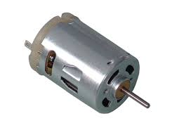
A direct current (DC) motor is a fairly simple electric motor that uses electricity and a magnetic field to produce torque, which causes it to turn. At its most simple, it requires two magnets of opposite polarity and an electric coil, which acts as an electromagnet. The repellent and attractive electromagnetic forces of the magnets provide the torque that causes the motor to turn.

Anyone who has ever played with magnets knows that they are polarized, with a positive and a negative side. The attraction between opposite poles and the repulsion of similar poles can easily be felt, even with relatively weak magnets. A DC motor uses these properties to convert electricity into motion. As the magnets within the motor attract and repel one another, the motor turns.
400px-Motor_Commutators download
In this blog I have decided to us Pulse Modulation to control a DC motor, this is basicly done by varying the Pulse width to the DC motor, basicly if the pulse width is 20mS the motor should be running a 100% but with the pulse width is 1omS(half the orginal) the motor should run at 50% and so on so forth. The PWM is supplied from Pin 37 on the dsPIC and that then goes to the driver chip.
The PWM was calculated as follows:
Capture
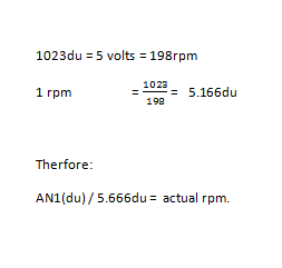
So after I had that worked out, I used Potentiometer to vary the voltage into the into ANO(1),the potentiometer uses the voltage divider rule(also shown in Servo post) and the Rangefinder to change the direction of the motor. I used this sensor because I already knew its parameters from my post on the Stepper Motor.Also i wanted to use the UART to tell me the rpm of the motor at a certain voltage. With th DC motor that I was using the rpm at 5v was 210 rpm( got from data sheet. So first I had to verify that is was actually 210rpm@ 5volts. I did this by using a tachometer and shining it on the shaft and applying 5volts to it. I actually got 198rpm at 5v.Next I had to measure the maximun voltage that would be leaving the potentiometer, which was 5v.So with some basic maths I was able to figure out the scaler that I would use in the c-code. Maths are below: Capturev Code used:

//
// dsPIC30F4011
// Control Speed and Direction of a DC motor
// Using Potentiometer and Rangefinder
//
// Written by JamesMcMahon
// Last updated 28-11-2013
//

#include
#include
#include
#include

// Configuration settings
_FOSC(CSW_FSCM_OFF & FRC_PLL16); // Fosc=16x7.5MHz, Fcy=30MHz
_FWDT(WDT_OFF);                  // Watchdog timer off
_FBORPOR(MCLR_DIS);              // Disable reset pin

// Function prototypes
unsigned int read_analog_channel(int n);

int main()
{
    int rangefinder=0;
    int pot=0;
	int rpm=0;

    // Make all port D pins outputs
    TRISD = 0;

    // Configure AN0-AN8 as analog inputs
    ADCON3bits.ADCS = 15;  // Tad = 266ns, conversion time is 12*Tad
    ADCON1bits.ADON = 1;   // Turn ADC ON

    // Configure PWM for free running mode
    //
    //   PWM period = Tcy * prescale * PTPER = 0.33ns * 64 * PTPER
    //   PWM pulse width = (Tcy/2) * prescale * PDCx
    //
    PWMCON1 = 0x00FF;     // Enable all PWM pairs in complementary mode
    PTCONbits.PTCKPS = 3; // prescale=1:64 (0=1:1, 1=1:4, 2=1:16, 3=1:64)
    PTPER = 9375;         // 20ms PWM period (15-bit period value)
    PDC1 = 1406;          // 1.5ms pulse width on PWM channel 1
    PTCONbits.PTEN = 1;   // Enable PWM time base

    // Setup UART
    U1BRG = 48;            // 38400 baud @ 30 MIPS
    U1MODEbits.UARTEN = 1; // Enable UART

    // Declare Max PDC (17814=19ms)
    int PDCmax = 17814;

    while(1)
    {

        // Read colour sensor
        rangefinder = read_analog_channel(2);

        //Read values from pot and PDC H
        pot = read_analog_channel(1);
		// Print out RPM on UART.
		printf("Motor RPM = %d\n ",rpm);
		rpm = ((pot/5.16)-198)*-1;
        // Set Motor Direction
        if (rangefinder <= 512) LATD=0b0010;      //  Drive Forward       
        else if(rangefinder > 512) LATD=0b0001;      // Reverse

        // Set value for PDC1 to control speed of motor
        PDC1 = PDCmax-((PDCmax)*((pot)/600.0));

    }

    return 0;
}

// This function reads a single sample from the specified
// analog input. It should take less than 5us when the
// microcontroller is running at 30 MIPS.
// The dsPIC30F4011 has a 10-bit ADC, so the value
// returned is between 0 and 1023 inclusive.
unsigned int read_analog_channel(int channel)
{
    ADCHS = channel;         // Select the requested channel
    ADCON1bits.SAMP = 1;      // Start sampling
    __delay32(30);            // 1us delay @ 30 MIPS
    ADCON1bits.SAMP = 0;      // Start Converting
    while (!ADCON1bits.DONE); // Should take 12 * Tad = 3.2us
    return ADCBUF0;
}

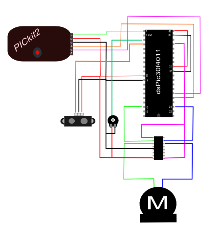
Circuit Diagram.

In the circuit below I forgot to include a capacitor across the supply voltage. Its there to stabilize the voltage .

Capture15

Here is a Video of the circuit working and a photo of the actual circuit I used.

20131129_021807

Servo Motor

What is a Servo Motor.

 A Servo is a small device that incorporates a two wire DC motor, a gear train, a potentiometer, an integrated circuit, and an output shaft. Of the three wires that stick out from the motor casing, one is for power, one is for ground, and one is a control input line. The shaft of the servo can be positioned to specific angular positions by sending a coded signal. As long as the coded signal exists on the input line, the servo will maintain the angular position of the shaft. If the coded signal changes, then the angular position of the shaft changes.

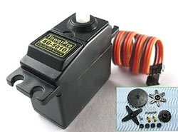
The specfic Servo Motor that I am using is Tower Pro SG-5010

  • Angle Range 180°
  • Torque   4.8 v  :  111.11oz-in
  • Speed      4.8 v  :  0.17sec/60 Degrees

towerpro-sg-5010

Controlling the servo using Output Compare

When using the dsPic30f4011 first we have to calculate the angle of the servo that we wish to obtain, it is got using the following formula:

OCxRSa = OCxRS_{min} + \frac{a}{180}(OCxRS_{max} - OCxRS_{min})

Here is the code that I used:

//
// dsPIC30F4011 servo control using output compare

//
// This dsPIC30F4011 example program controls a
// servo using the output compare module.
//
// The max and min OC1RS values (OC1RS=260 for
// 0 degrees and OC1RS=1070 for 180 degrees)
// were determined by trial and error once the
// servo was mounted in position.
//

#include <xc.h>
#include <libpic30.h>

// Configuration settings
_FOSC(CSW_FSCM_OFF & FRC_PLL16); // Fosc=16x7.5MHz, Fcy=30MHz
_FWDT(WDT_OFF);                  // Watchdog timer off
_FBORPOR(MCLR_DIS);              // Disable reset pin

int main()
{
    // Configure RD0 and RD1 as outputs
    TRISD = 0b1100;

    // Configure Timer 2 (default timer for output compare)
    T2CONbits.TCKPS = 0b10; // Timer 2 prescaler 1:64
    PR2 = 9375;             // Timer 2 period (20ms)
    T2CONbits.TON = 1;      // Enable Timer 2

    // Configure Output Compare channel 1 (OC1)
    OC1CONbits.OCM = 0b101; // continuous pulse mode
    OC1R = 0;               // pulse start time
    OC1RS = 800;            // pulse stop time

    // Create an array of angle positions to step through
    double angle[] = {0.0, 15.0, 30.0 ,45.0 ,60.0 ,75.0 ,90.0 ,105.0 ,120.0 ,135.0 , 150.0,
                      165.0, 180.0, 120.0, 90.0, 60.0, 30.0, 0.0};
    int n = 0; // step counter

    // Configure max and min OC1RS values
    int min = 260;  // OC1RS value for 0 degrees
    int max = 1070; // OC1RS value for 180 degrees

    // Now just cycle through the angle positions
    while(1)
    {
        // Step to next n value
        n = n + 1;
        if (n == 11) n = 0;

        // update servo angle
        OC1RS = min + (angle[n]/180.0)*(max-min);

        __delay32(30000000); // 1s delay
    }

    return 0;
}

Video

In this video, the servo moves from 0 degrees to 180 degrees in crements of 15 degrees and then back from 180 degrees to 0 degrees in increments of 30 dergrees.

Circuit Diagram

Capture123

Controlling the servo with a potentiometer

In the following video I used a potentiometer to adjust the angle of the servo between zero degrees and 180 degrees. With a change in voltage from zero to five volts causes by varying the resistance on the potentiometer. The varying voltage signal is sent to Pin 2 (ANO) which converts the voltage to a digital output. The PWM function this is done from the output of pin 37, this controls the servo angle the waveforms frequency is 20ms.

voltagedividerformula

Circuit Diagram

Capture23

Simulation of Landing Gear

Using a stepper motor and a range sensor I wanted to simulate the landing gear of an aircraft. What I wanted it to do was when the aircraft decended until a certain point above the ground that the landing gear would automatically deploy and stay deployed until that distance is exceeded again. But first here is abit of a background on the stepper motor and the range finder.

Stepper Motor

A stepper motor is a special type of electric motor that moves in increments, or steps, rather than turning smoothly as a conventional motor does. The size of the increment is measured in degrees and can vary depending on the application. The speed of the motor is determined by the time delay between each incremental movement.

 The coils are switched on and off in a specific sequence to cause the motor shaft to turn through the desired angle. The motor can operate in either direction (clockwise or counterclockwise). When the coils of a stepper motor receive current , the rotor shaft turns to a certain position and then stays there unless or until different coils are energized.

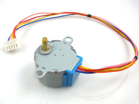
The specic stepper motor that I am using is 28BYJ-48 – 5V Stepper Motor and its datasheet can be found here:   http://robocraft.ru/files/datasheet/28BYJ-48.pdf

ImagMotore of Stepper 28byj-48

ImagMotore of Stepper 28byj-48

Operation of Coils

Operation of Coils

Range Sensor(Sharp GP2D12)

Range Sensor(Sharp GP2D12) . After the initial testing of it and when compared to the datasheet of the sensor, which was got online http://www.sharpsma.com/webfm_send/1203, matched up pretty well. Here are the results of the range sensor:gp2d12

Distance (cm)

Ouput Voltage (V)

0 0
5 3.1
10 2.45
15 1.7
20 1.36
30 0.83
40 0.69
50 0.59
60 0.5

Capture251

Y-Axis (Voltage)      X-Axis (distance)

These results were got with an input voltage of 5 volts in to sensor.

Code Used

CaptureCapture1Capture23Capture4

Circuit Diagram

Capturebi

Photos & Videos

20131119_182256


D-Day!!

Well the day finally came, RoboSumo Competition!!

Things didn’t really go the way we had planned. The morning of the competition we had our robot working well but the first hic-cup came when the ground wire came loose from the range sensor and the solder broke.So I went up to solder this back together, but I ended up doing more damage than good.The area was so tight and soldering skills not the best, I put on too much solder and made a mess of the circuitry that was there already. In the end the range sensor stopped working. The pursuit of a new range sensor at such a late stage didnt prove to fruitful. So as a team we discussed what options we had and ended up deciding that a switch at the front of the robot (like the race to the wall) was our best option. The plan was that (hopefully) the enemy robot would hit the switch and that would make our robot push the enemy off, a long shot I know but desperate times desperate measures.

So with the robot with the 3 sensors(1 back, 2 front) and our deadly switch at the front, the  team showing signs of optimism again. Then when we went to change the code to incorporate the switch into it and discard the range sensor code, our pic would not connect. So with time down to 35mins and counting, scrambling around to gain a new chip, trying different computers, different pic2 kit and our last gasp effort was to wire the chip on an independent breadborad and then try program it. But we failed.

So competition time came and we had our robot programmed to spin at the start and with our now non-existence range finder to find the enemy robot and the switch at the front of the robot wired  but no code to tell the robot what to do if it hit.

So basically we had our robot that spun round in a circle.

We started 11th and with shere luck and ever thing else we manged to make it up to 2nd by the finish of round 1. The vibes from our competitors at this stage were getting more sour with every battle.

We dropped to 3rd after round 2 and back to 2nd after round 3.We had made it to the quarter-final.

At this stage we thought that we might have some luck with the obtaining a functioning chip by borrowing  a fellow competitors chip that was already out of the tournament. But it proved a lot tougher than we tought. After several requests, eventually one good samaritan donated their chip. Life line got.

But im afraid by this stage we had run outa time, we  got our chip to connect but when writing the code to it, it esared the original code that was on it and yet didn’t write anything to it. The original enthusiasm and optimism at the start of the day had gone and we were heading into the quarter-final with an even less non functioning robot. Inevitably we were knocked out by eHonda.

So that was the end of our robosum journey. Maybe with a bit of luck during the day, we could have put on a better spectacle. But overall I was happy with the way the robot turned out. Competition day was hectic from start to finish, in between bouts trying to get the robot to run and still don’t no whether it was the pic or the chip.

Below are pics…IMG_20130507_152600 IMG_20130508_154516

Bits coming together.

After our last meeting, I went and acquired a Range Sensor(Sharp GP2D12) that was supplied by the college (thanking you). After the initial testing of it and when compared to the datasheet of the sensor, which was got online, matched up pretty well. Here are the results of our range sensor:

gp2d12

Distance (cm)

Ouput Voltage (V)

0 0
5 3.1
10 2.45
15 1.7
20 1.36
30 0.83
40 0.69
50 0.59
60 0.5

Capture251

Y-Axis (Voltage)      X-Axis (distance)

These results were got with an input voltage of 5 volts in to sensor.

After these tests we can clearly see that the output voltage is not linear but we don’t think that will effect us too much. We also decided to put a capacitor across the input voltage to the sensor so that it would give us a more regulated voltage in which in turn give us a more constants voltage output.

Motors

In the end we decided to use the motor that were supplied from the college. After testing them from a battery pack we came to the conclusion that they were more than adequate. The motors weren’t the fastest but there torque values were quiet good and the max voltage input for these motors is 6volts. The only problem we encountered with the motors was that the shaft was small and was very close to the motors shell as you can see from the photo below. Which meant that our wheels needed to be super slim.

IMAG0319

Reflective Sensor

In the end we went with 3 reflective sensors. We decided to have 1 at the back of the robot directly behind the motors and in the middle. After inspecting the robosumo arena we thought that 1 sensor at the back would be sufficient due to the wide white area surrounding the arena. But at the front of the robot we concluded that the extreme left and right needed a sensor each. The reflective sensors that we used were the same as used in the race to the wall.

IMAG0209

Rebuilding!!

With the race to the wall over, our attention switched to the rebuilding and modifying of our robot to compete in the robosumo competition. So we got our team together and had a meeting on what changes needed to be made and here is what came from that meeting:

  1. Needed to incorpate more reflective sensors into the robot.We decided that we at least needed a minimum of 3 reflective sensors, 2 on the front and at least 1 or 2 on the back.
  2. Range Sensor needed to be implimented in aswell and had to research and test this sensor in time so that it wasnt a big rush near the end.
  3. The frame of the robot was decided to be built again out of the mechano that we used in the race to the wall.
  4. Each of the back wheels needed there own motor,which would enable us to to move left and right.
  5. The front of the robot was going to have a jockey wheel.
  6. The outer body of the robot was going to be built out of aluminium mesh, we decided on this because of it good weight and accessibility of the material.
  7. The wheels that we used in the race to the wall were to be scraped for thinner wheels that give more grip.

Testing!!!

Testing

Well after we got the circuit onto a smaller bread board, we attached it to the robot. Once we started to test the robot that when the fun really started. Alot of valueable lessons learnt.

But first we had to determine what distance the light sensor had to be above the ground for it to be able to function efficentlly, after a long time of testing and ajusting the level of the sensor from touching the ground to about 1cm off the ground, it was clear that our sensor was actually broken and was never working in the first place.

Lesson : Check if equipment is working properly.

When we gained a functioning light sensor, we quickly determined that the sensor needed to be 2mm off the ground for it to work.

Next part of the testing was to get the our robot driving straight. When we started testing it was very clear that our robot was vering to the left. So after alot of deliberation we decided to replace the back wheel with a more stable and broad 2 wheeled axil which steadied the robot up alot.

So here is our robot in its testing…..

As you can see from the video we had did have a few problems with our code but the main princples of the ocde were working. The problem was that we had a delay in when the switch hit the wall, so the robot would reverse for 5 seconds.

But after getting the code fixed and working right. We then recorded our time for the robosumo and am very glad to say 11th overall.

Here is the circuit we ended up with.

IMG_20130410_172113 (1)